Construção de um módulo
free-mo.br :: free-mo.br :: free-mo.br
Página 1 de 1

 Construção de um módulo
Rica Sáb Jun 01, 2013 9:24 am
Encontrei em um grupo de Free-mo norte-americano um tópico com o progresso da construção do módulo Free-mo de um dos seus integrantes.
É interessante a maneira como ele apresenta a necessidade de "dobrar" as normas padrão do Free-mo para atender a sua necessidade, encontrando uma alternativa para manter o módulo no padrão Standard Free-mo na extremidade.
Pelo que pude entender esse módulo teria cerca de 2m43,5cm de comprimento e algo em torno de 1m18cm de largura.
Seu objetivo foi reproduzir trechos de ferrovia baseados em cidades do sudeste, três na Geórgia e duas na Carolina do Sul, e por "falta" de espaço, se viu obrigado a passar por cima das normas do Free-mo. Como alternativa decidiu criar "Módulo Companion" para que a linha principal fosse reposicionada na extremidade do módulo de acordo com a norma Standard Free-mo.
Mais uma vez fica claro que o free-mo.br, assim como ocorre no Free-mo, permite que o modelista construa o módulo com as dimensões que desejar, não estando em momento algum preso à um padrão de largura e comprimento. O que é preciso observar é que na extremidade do módulo é necessário obedecer o padrão da Placa terminal, a fim de permitir a conexão com outro módulo free-mo.br. Nesse caso a alternativa encontrada foi criar uma seção (Módulo Companion) que fizesse a conexão "fora do padrão na extremidade do módulo principal e na outra extremidade obedecesse o padrão Standard Free-mo.
Este é o "Track Plan"

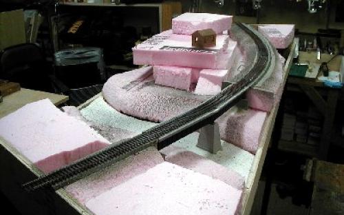
Este o módulo em fase adiantada:

A seguir o texto original publicado por John Degnan, ferromodelista norte-americano, praticante do Free-mo, mostrando o passo-a-passo da construção de seu módulo.
Ok, I have decided to repost my earlier progress report... this time with links
to the images hosted on MY site instead of the Yahoo group site.
Due (believe it or not) to a lack of room on my module (which is a full 8' long
by 46-3/4" wide), I am being forced to BEND the Free-Mo rules (standards) a bit.
But it is my understanding that what I need to do is allowed when there is a
secondary module that acts as an extension of the first and will always be the
ONLY module connected to the non-standard end of the primary module. The
'offense' that I'm having to commit is having TWO, paralleling tracks on a 24"
wide, single track sized end plate... one being a siding that will be located
slightly over THREE (actual) inches off the mainline. The mainline track will
be dead center at the 12" mark on the end plate and the passing siding offset to
one side. For the passing siding to fit where I want it to and still have room
for the structures that I want beside it, I am having to build a second, short
'Companion Module' to merge the siding back to the mainline. I did my best to
avoid this, but after thinking about it long enough to realize some benefits
that could come with doing this, I've had a change of heart, and I now like it
much better than the single module alternative.
The inspirationS for my module are FIVE small southeastern towns - three in
Georgia and two in South Carolina :
Meldrim, GA (my hometown) which was once served by two railroad (SAL and
CofG) :
www.trainweb.org/seaboard/FreeMoModule/MeldrimGA.JPG
Bellville, GA which is located on the same line as my hometown and having
the railroad depot and
freight station combination that I find appealing :
www.trainweb.org/seaboard/FreeMoModule/BellvilleGA.JPG
Fairfax, SC which once was served by two railroads (SAL and C&WC) that
crossed each other
in the middle of town and had now has connecting tracks.
www.trainweb.org/seaboard/FreeMoModule/FairfaxSC.JPG
Yemassee, SC which was also served by two railroads (ACL and C&WC) that not
only crossed
one another but also had connecting tracks :
www.trainweb.org/seaboard/FreeMoModule/YemasseeSC.JPG
Fairfax, SC has the general look and feel I am trying to catch, but my hometown
of Meldrim, GA was the original inspiration. I am also giving credit to
Pembroke, GA for inspiring some of my ideas for trackside and roadside town
structures.
TRACK PLAN :
After working out a way tocombine all of these town-scenes and their railroad
content into what most closely represents what I'm trying to achieve, the
following track plan is what I've settled on :
www.trainweb.org/seaboard/FreeMoModule/CrossingModule.JPG
IMAGES :
Here are some photos of the progress I've made :
The shape of things to come (the top deck).
www.trainweb.org/seaboard/FreeMoModule/DSC05586.JPG
Side shot showing15 degree cuts on end to achieve 30 degree crossing angle.
www.trainweb.org/seaboard/FreeMoModule/DSC05588.JPG
End shot showing15 degree cuts on end to achieve 30 degree crossing angle.
www.trainweb.org/seaboard/FreeMoModule/DSC05589.JPG
Shot of beginnings of center spine support and ribs.
www.trainweb.org/seaboard/FreeMoModule/DSC05604.JPG
End shot of the center spine and ribs in position.
www.trainweb.org/seaboard/FreeMoModule/DSC05605.JPG
Angle shot of the center spine and ribs in position.
www.trainweb.org/seaboard/FreeMoModule/DSC05606.JPG
Shot of work on center spine and ribs intended to lighten the load.
www.trainweb.org/seaboard/FreeMoModule/DSC05980.JPG
End shot of finished and attached center spine and ribs.
www.trainweb.org/seaboard/FreeMoModule/DSC05988.JPG
Angle shot of finished and attached center spine and ribs.
www.trainweb.org/seaboard/FreeMoModule/DSC05990.JPG
Angle shot of end plates and sides attached.
www.trainweb.org/seaboard/FreeMoModule/DSC06114.JPG
End shot of end plates and sides attached.
www.trainweb.org/seaboard/FreeMoModule/DSC06115.JPG
Shot 1 of blocking on spine for attaching end plates.
www.trainweb.org/seaboard/FreeMoModule/DSC06117.JPG
Shot 2 of blocking on spine for attaching end plates.
www.trainweb.org/seaboard/FreeMoModule/DSC06119.JPG
Shot 1 of nearly complete module - still some trimming and sanding left to
do.
www.trainweb.org/seaboard/FreeMoModule/DSC06123.JPG
Shot 2 of nearly complete module - still some trimming and sanding left to
do.
www.trainweb.org/seaboard/FreeMoModule/DSC06124.JPG
Shot 3 of nearly complete module - still some trimming and sanding left to
do.
www.trainweb.org/seaboard/FreeMoModule/DSC06125.JPG
Shot 4 of nearly complete module - still some trimming and sanding left to
do.
www.trainweb.org/seaboard/FreeMoModule/DSC06127.JPG
Shot 1 of (current) leg pockets (I'm considering a few different designs
for these, so it may change)
www.trainweb.org/seaboard/FreeMoModule/DSC06169.JPG
Shot 2 of (current) leg pockets
www.trainweb.org/seaboard/FreeMoModule/DSC06170.JPG
Shot 3 of (current) leg pockets
www.trainweb.org/seaboard/FreeMoModule/DSC06172.JPG
Shot 1 of completed roadbed (on primary module)
www.trainweb.org/seaboard/FreeMoModule/0414131925a.jpg
Shot 2 of completed roadbed (on primary module)
www.trainweb.org/seaboard/FreeMoModule/0414131927.jpg
Shot 3 of completed roadbed (on primary module)
www.trainweb.org/seaboard/FreeMoModule/0414131927a.jpg
... And that is where things have stopped for the time being thanks to a few
unforseen supply issues. So, more coming soon.
É interessante a maneira como ele apresenta a necessidade de "dobrar" as normas padrão do Free-mo para atender a sua necessidade, encontrando uma alternativa para manter o módulo no padrão Standard Free-mo na extremidade.
Pelo que pude entender esse módulo teria cerca de 2m43,5cm de comprimento e algo em torno de 1m18cm de largura.
Seu objetivo foi reproduzir trechos de ferrovia baseados em cidades do sudeste, três na Geórgia e duas na Carolina do Sul, e por "falta" de espaço, se viu obrigado a passar por cima das normas do Free-mo. Como alternativa decidiu criar "Módulo Companion" para que a linha principal fosse reposicionada na extremidade do módulo de acordo com a norma Standard Free-mo.
Mais uma vez fica claro que o free-mo.br, assim como ocorre no Free-mo, permite que o modelista construa o módulo com as dimensões que desejar, não estando em momento algum preso à um padrão de largura e comprimento. O que é preciso observar é que na extremidade do módulo é necessário obedecer o padrão da Placa terminal, a fim de permitir a conexão com outro módulo free-mo.br. Nesse caso a alternativa encontrada foi criar uma seção (Módulo Companion) que fizesse a conexão "fora do padrão na extremidade do módulo principal e na outra extremidade obedecesse o padrão Standard Free-mo.
Este é o "Track Plan"
Este o módulo em fase adiantada:
A seguir o texto original publicado por John Degnan, ferromodelista norte-americano, praticante do Free-mo, mostrando o passo-a-passo da construção de seu módulo.
Ok, I have decided to repost my earlier progress report... this time with links
to the images hosted on MY site instead of the Yahoo group site.
Due (believe it or not) to a lack of room on my module (which is a full 8' long
by 46-3/4" wide), I am being forced to BEND the Free-Mo rules (standards) a bit.
But it is my understanding that what I need to do is allowed when there is a
secondary module that acts as an extension of the first and will always be the
ONLY module connected to the non-standard end of the primary module. The
'offense' that I'm having to commit is having TWO, paralleling tracks on a 24"
wide, single track sized end plate... one being a siding that will be located
slightly over THREE (actual) inches off the mainline. The mainline track will
be dead center at the 12" mark on the end plate and the passing siding offset to
one side. For the passing siding to fit where I want it to and still have room
for the structures that I want beside it, I am having to build a second, short
'Companion Module' to merge the siding back to the mainline. I did my best to
avoid this, but after thinking about it long enough to realize some benefits
that could come with doing this, I've had a change of heart, and I now like it
much better than the single module alternative.
The inspirationS for my module are FIVE small southeastern towns - three in
Georgia and two in South Carolina :
Meldrim, GA (my hometown) which was once served by two railroad (SAL and
CofG) :
www.trainweb.org/seaboard/FreeMoModule/MeldrimGA.JPG
Bellville, GA which is located on the same line as my hometown and having
the railroad depot and
freight station combination that I find appealing :
www.trainweb.org/seaboard/FreeMoModule/BellvilleGA.JPG
Fairfax, SC which once was served by two railroads (SAL and C&WC) that
crossed each other
in the middle of town and had now has connecting tracks.
www.trainweb.org/seaboard/FreeMoModule/FairfaxSC.JPG
Yemassee, SC which was also served by two railroads (ACL and C&WC) that not
only crossed
one another but also had connecting tracks :
www.trainweb.org/seaboard/FreeMoModule/YemasseeSC.JPG
Fairfax, SC has the general look and feel I am trying to catch, but my hometown
of Meldrim, GA was the original inspiration. I am also giving credit to
Pembroke, GA for inspiring some of my ideas for trackside and roadside town
structures.
TRACK PLAN :
After working out a way tocombine all of these town-scenes and their railroad
content into what most closely represents what I'm trying to achieve, the
following track plan is what I've settled on :
www.trainweb.org/seaboard/FreeMoModule/CrossingModule.JPG
IMAGES :
Here are some photos of the progress I've made :
The shape of things to come (the top deck).
www.trainweb.org/seaboard/FreeMoModule/DSC05586.JPG
Side shot showing15 degree cuts on end to achieve 30 degree crossing angle.
www.trainweb.org/seaboard/FreeMoModule/DSC05588.JPG
End shot showing15 degree cuts on end to achieve 30 degree crossing angle.
www.trainweb.org/seaboard/FreeMoModule/DSC05589.JPG
Shot of beginnings of center spine support and ribs.
www.trainweb.org/seaboard/FreeMoModule/DSC05604.JPG
End shot of the center spine and ribs in position.
www.trainweb.org/seaboard/FreeMoModule/DSC05605.JPG
Angle shot of the center spine and ribs in position.
www.trainweb.org/seaboard/FreeMoModule/DSC05606.JPG
Shot of work on center spine and ribs intended to lighten the load.
www.trainweb.org/seaboard/FreeMoModule/DSC05980.JPG
End shot of finished and attached center spine and ribs.
www.trainweb.org/seaboard/FreeMoModule/DSC05988.JPG
Angle shot of finished and attached center spine and ribs.
www.trainweb.org/seaboard/FreeMoModule/DSC05990.JPG
Angle shot of end plates and sides attached.
www.trainweb.org/seaboard/FreeMoModule/DSC06114.JPG
End shot of end plates and sides attached.
www.trainweb.org/seaboard/FreeMoModule/DSC06115.JPG
Shot 1 of blocking on spine for attaching end plates.
www.trainweb.org/seaboard/FreeMoModule/DSC06117.JPG
Shot 2 of blocking on spine for attaching end plates.
www.trainweb.org/seaboard/FreeMoModule/DSC06119.JPG
Shot 1 of nearly complete module - still some trimming and sanding left to
do.
www.trainweb.org/seaboard/FreeMoModule/DSC06123.JPG
Shot 2 of nearly complete module - still some trimming and sanding left to
do.
www.trainweb.org/seaboard/FreeMoModule/DSC06124.JPG
Shot 3 of nearly complete module - still some trimming and sanding left to
do.
www.trainweb.org/seaboard/FreeMoModule/DSC06125.JPG
Shot 4 of nearly complete module - still some trimming and sanding left to
do.
www.trainweb.org/seaboard/FreeMoModule/DSC06127.JPG
Shot 1 of (current) leg pockets (I'm considering a few different designs
for these, so it may change)
www.trainweb.org/seaboard/FreeMoModule/DSC06169.JPG
Shot 2 of (current) leg pockets
www.trainweb.org/seaboard/FreeMoModule/DSC06170.JPG
Shot 3 of (current) leg pockets
www.trainweb.org/seaboard/FreeMoModule/DSC06172.JPG
Shot 1 of completed roadbed (on primary module)
www.trainweb.org/seaboard/FreeMoModule/0414131925a.jpg
Shot 2 of completed roadbed (on primary module)
www.trainweb.org/seaboard/FreeMoModule/0414131927.jpg
Shot 3 of completed roadbed (on primary module)
www.trainweb.org/seaboard/FreeMoModule/0414131927a.jpg
... And that is where things have stopped for the time being thanks to a few
unforseen supply issues. So, more coming soon.

Rica- Ger. Eng. Ferroviária

- Mensagens : 294
Data de inscrição : 20/07/2012
Idade : 59
Localização : Mogi das Cruzes/SP -

7th Street - MN Free-mo
Rica Sáb Jun 01, 2013 10:41 pm
Aqui vai outro exemplo de um projeto feito a partir de um trecho de ferrovia real...
http://www.mnfreemo.org/publicfiles/publicfiles/7thPrototype_0.pdf
Note que na seção posicionada na parte superior do gráfico do módulo, foi definido um "double track end", ou final de linha dupla. O módulo é composto por cinco seções que possuem dimensões diferentes uma da outra, bem como formatos assimétricos. A última seção foi construída em um ângulo que permitiu manter reta a linha que ladeia o pátio fazendo com que ela ficasse posicionado exatamente no ponto central da Placa Terminal no padrão "Single Track end", final de linha simples. Entretanto acredito que para se adequar ao Standerd Free-mo, este trecho final de linha precisaria estar 15cm em linha reta perpendicular à Placa Terminal, mas a ideia é muito boa.
Um bom exemplo de como projetar um módulo free-mo.br
Rica- Ger. Eng. Ferroviária
- Mensagens : 294
Data de inscrição : 20/07/2012
Idade : 59
Localização : Mogi das Cruzes/SP -
Forest Bend - Minnesota Free-mo
Rica Seg Jun 03, 2013 8:48 pm
Ainda vasculhando pelo site do Minnesota Free-mo encontrei imagens do módulo Forest Bend.
O acabamento é muito bacana...

Nessas imagens podemos ver um pouco de como é feita a estrutura em madeira e o uso do styrofoam no cenário...

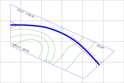
O diagrama do módulo:
O acabamento é muito bacana...
Nessas imagens podemos ver um pouco de como é feita a estrutura em madeira e o uso do styrofoam no cenário...
O diagrama do módulo:
Rica- Ger. Eng. Ferroviária
- Mensagens : 294
Data de inscrição : 20/07/2012
Idade : 59
Localização : Mogi das Cruzes/SP -
Re: Construção de um módulo
Rica Ter Set 17, 2013 2:34 pm
O Alexandre (SF-Trens) me passou um link com uma matéria sobre a construção de módulos.
Ainda não me dediquei à tradução, mas as fotos já dão uma boa ideia sobre o trabalho.


Acho que vale a pena acessar o link e procurar prestar atenção em alguns detalhes da construção.
Não sei se está no padrão Standard Free-Mo, mas o modo de construção da estrutura parece bem legal.
vale a pena acessar pra ver:
http://mrhmag.us2.list-manage.com/track/click?u=571743ad1254f1d0593e8f68d&id=384701cdbc&e=fa697cb686
Ainda não me dediquei à tradução, mas as fotos já dão uma boa ideia sobre o trabalho.
Acho que vale a pena acessar o link e procurar prestar atenção em alguns detalhes da construção.
Não sei se está no padrão Standard Free-Mo, mas o modo de construção da estrutura parece bem legal.
vale a pena acessar pra ver:
http://mrhmag.us2.list-manage.com/track/click?u=571743ad1254f1d0593e8f68d&id=384701cdbc&e=fa697cb686
Rica- Ger. Eng. Ferroviária
- Mensagens : 294
Data de inscrição : 20/07/2012
Idade : 59
Localização : Mogi das Cruzes/SP -
» Superfície do módulo...
» Modulo com DCC++EX & EngineDrive
» Falando sobre dimensões de módulos
» Módulo free-mo.br
» Módulo Porto Seco (CRAGEA SJC)
» Modulo com DCC++EX & EngineDrive
» Falando sobre dimensões de módulos
» Módulo free-mo.br
» Módulo Porto Seco (CRAGEA SJC)
free-mo.br :: free-mo.br :: free-mo.br
Página 1 de 1
Permissões neste sub-fórum
Não podes responder a tópicos|
|
|